- 您现在的位置:买卖IC网 > Sheet目录264 > YC124-JR-07120KL (Yageo)RES ARRAY 120K OHM 4 RES 0804
Product specification
6
Chip Resistor Surface Mount
YC/TC
SERIES
124 (RoHS Compliant)
9
ELECTRICAL CHARACTERISTICS
Table 2
FOOTPRINT AND SOLDERING
PROFILES
CHARACTERISTICS
Operating Temperature Range
Rated Power
YC124 TC124
–55 °C to +155 °C –55 °C to +125 °C
1/16 W 1/16 W
Recommended footprint and
soldering profiles, please refer to
data sheet “Chip resistors
mounting ”.
Maximum Working Voltage
Maximum Overload Voltage
Dielectric Withstanding Voltage
25 V
50 V
100 V
50 V
100 V
100 V
Resistance Range
5% (E24)
1% (E24/E96)
1 ? to 1 M ?
10 ? to 1 M ?
Zero Ohm Jumper < 0.05 ?
Temperature Coefficient
1 ? ≤ R < 10 ? ±250 ppm/°C
10 ? ≤ R ≤ 1 M ? ±200 ppm/°C
±200 ppm/°C
Jumper Criteria
Rated Current
Maximum Current
1.0 A
2.0 A
1.0 A
1.5 A
PACKING STYLE AND PACKAGING QUANTITY
Table 3 Packing style and packaging quantity
PRODUCT TYPE
YC/TC124
PACKING STYLE
Paper Taping Reel (R)
REEL DIMENSION
7" (178 mm)
10" (254 mm)
13" (330 mm)
QUANTITY PER REEL
10,000 units
20,000 units
40,000 units
NOTE
1. For paper tape and reel specification/dimensions, please refer to data sheet “Chip resistors packing”.
FUNCTIONAL DESCRIPTION
O P E R A T I N G T E M P E R A T U R E R A N G E
YC124: –55 °C to +155 °C
handbook, halfpage
TC124: –55 °C to +125 °C
P O W E R R A T I N G
YC/TC 124 rated power at 70 °C is 1/16 W
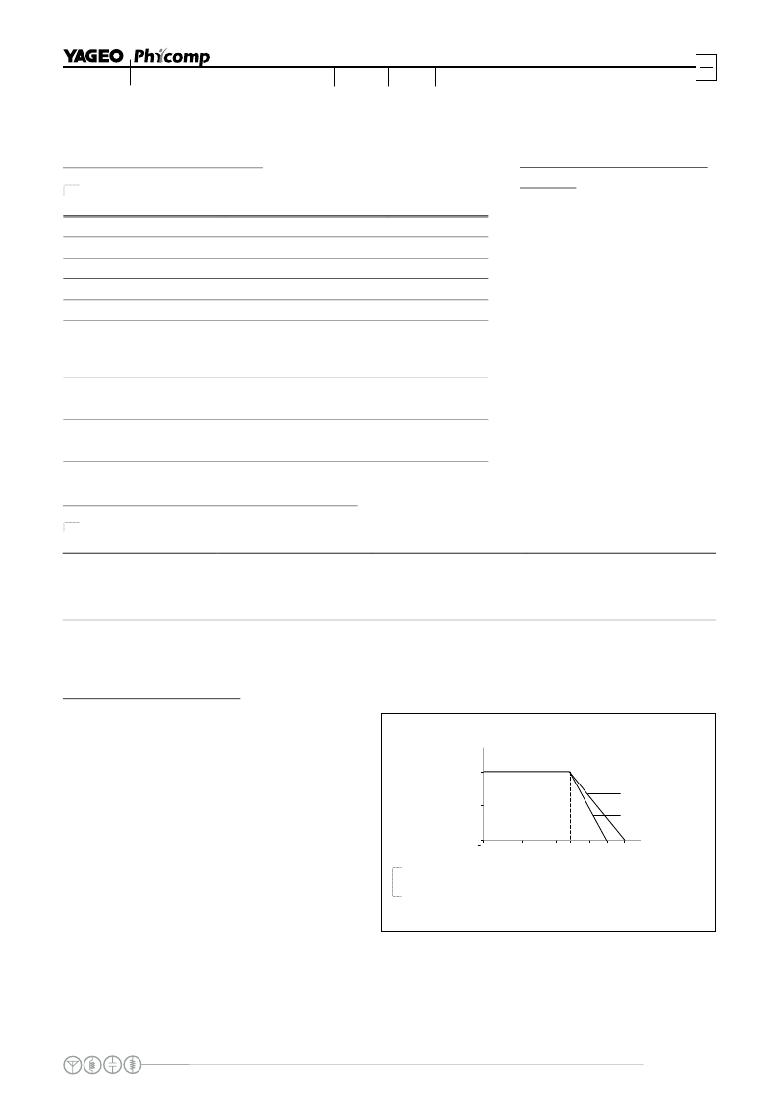
P
(%P rated )
100
50
MLB206_3
YC124
TC124
Tamb ( C)
R ATED VOLTAGE
The DC or AC (rms) continuous working voltage
0
55
0
50
70
100
125 155
o
corresponding to the rated power is determined by
the following formula:
V= √ (P X R)
or max. working voltage whichever is less
Fig. 7 Maximum dissipation (P) in percentage of rated power as a
function of the operating ambient temperature (T amb )
Where
V=Continuous rated DC or
AC (rms) working voltage (V)
P=Rated power (W)
R=Resistance value ( X )
www.yageo.com
Mar 09, 2011 V.3
发布紧急采购,3分钟左右您将得到回复。
相关PDF资料
YC248-JR-0710RL
RES ARRAY 10 OHM 8 RES 1506
YC324-JK-072K2L
RES ARRAY 2.2K OHM 4 RES 2012
YE-2RB-A2
SWITCH PLUNGER SPST 25A SCREW
YE-2RV198-A41
SWITCH STRGHT LVR SPST 25A SCREW
YRM33F2BBBNN
SWITCH ROCKER DPDT 20A 125V
YZ-2R-A21
SWITCH PLUNGER SPST 15A SCREW
YZ-2R-A2
SWITCH PLUNGER SPST 15A SCREW
YZ-2RDS555116-D6-S
SWITCH PLUNGER SPST 15A QC
相关代理商/技术参数
YC124-JR-07120RL
功能描述:RES ARRAY 120 OHM 4 RES 0804 RoHS:是 类别:电阻器 >> 网络、阵列 系列:YC124 标准包装:10,000 系列:741 电路类型:隔离 电阻(欧姆):1M 电阻数:4 引脚数:8 每个元件的功率:62.5mW 容差:±5% 温度系数:±200ppm/°C 应用:- 安装类型:表面贴装 封装/外壳:0804(2010 公制),凹陷 供应商设备封装:0402 x 4 尺寸/尺寸:0.079" L x 0.039" W(2.00mm x 1.00mm) 高度:0.015"(0.38mm) 包装:带卷 (TR) 工作温度:-55°C ~ 125°C 其它名称:741C083105JPTR
YC124-JR-0712KL
功能描述:RES ARRAY 12K OHM 4 RES 0804 RoHS:是 类别:电阻器 >> 网络、阵列 系列:YC124 标准包装:10,000 系列:741 电路类型:隔离 电阻(欧姆):1M 电阻数:4 引脚数:8 每个元件的功率:62.5mW 容差:±5% 温度系数:±200ppm/°C 应用:- 安装类型:表面贴装 封装/外壳:0804(2010 公制),凹陷 供应商设备封装:0402 x 4 尺寸/尺寸:0.079" L x 0.039" W(2.00mm x 1.00mm) 高度:0.015"(0.38mm) 包装:带卷 (TR) 工作温度:-55°C ~ 125°C 其它名称:741C083105JPTR
YC124-JR-0712RL
功能描述:RES ARRAY 12 OHM 4 RES 0804 RoHS:是 类别:电阻器 >> 网络、阵列 系列:YC124 标准包装:10,000 系列:741 电路类型:隔离 电阻(欧姆):1M 电阻数:4 引脚数:8 每个元件的功率:62.5mW 容差:±5% 温度系数:±200ppm/°C 应用:- 安装类型:表面贴装 封装/外壳:0804(2010 公制),凹陷 供应商设备封装:0402 x 4 尺寸/尺寸:0.079" L x 0.039" W(2.00mm x 1.00mm) 高度:0.015"(0.38mm) 包装:带卷 (TR) 工作温度:-55°C ~ 125°C 其它名称:741C083105JPTR
YC124-JR-07130KL
功能描述:RES ARRAY 130K OHM 4 RES 0804 RoHS:是 类别:电阻器 >> 网络、阵列 系列:YC124 标准包装:10,000 系列:741 电路类型:隔离 电阻(欧姆):1M 电阻数:4 引脚数:8 每个元件的功率:62.5mW 容差:±5% 温度系数:±200ppm/°C 应用:- 安装类型:表面贴装 封装/外壳:0804(2010 公制),凹陷 供应商设备封装:0402 x 4 尺寸/尺寸:0.079" L x 0.039" W(2.00mm x 1.00mm) 高度:0.015"(0.38mm) 包装:带卷 (TR) 工作温度:-55°C ~ 125°C 其它名称:741C083105JPTR
YC124-JR-07130RL
功能描述:RES ARRAY 130 OHM 4 RES 0804 RoHS:是 类别:电阻器 >> 网络、阵列 系列:YC124 标准包装:10,000 系列:741 电路类型:隔离 电阻(欧姆):1M 电阻数:4 引脚数:8 每个元件的功率:62.5mW 容差:±5% 温度系数:±200ppm/°C 应用:- 安装类型:表面贴装 封装/外壳:0804(2010 公制),凹陷 供应商设备封装:0402 x 4 尺寸/尺寸:0.079" L x 0.039" W(2.00mm x 1.00mm) 高度:0.015"(0.38mm) 包装:带卷 (TR) 工作温度:-55°C ~ 125°C 其它名称:741C083105JPTR
YC124-JR-0713KL
功能描述:RES ARRAY 13K OHM 4 RES 0804 RoHS:是 类别:电阻器 >> 网络、阵列 系列:YC124 标准包装:10,000 系列:741 电路类型:隔离 电阻(欧姆):1M 电阻数:4 引脚数:8 每个元件的功率:62.5mW 容差:±5% 温度系数:±200ppm/°C 应用:- 安装类型:表面贴装 封装/外壳:0804(2010 公制),凹陷 供应商设备封装:0402 x 4 尺寸/尺寸:0.079" L x 0.039" W(2.00mm x 1.00mm) 高度:0.015"(0.38mm) 包装:带卷 (TR) 工作温度:-55°C ~ 125°C 其它名称:741C083105JPTR
YC124-JR-0713RL
功能描述:RES ARRAY 13 OHM 4 RES 0804 RoHS:是 类别:电阻器 >> 网络、阵列 系列:YC124 标准包装:10,000 系列:741 电路类型:隔离 电阻(欧姆):1M 电阻数:4 引脚数:8 每个元件的功率:62.5mW 容差:±5% 温度系数:±200ppm/°C 应用:- 安装类型:表面贴装 封装/外壳:0804(2010 公制),凹陷 供应商设备封装:0402 x 4 尺寸/尺寸:0.079" L x 0.039" W(2.00mm x 1.00mm) 高度:0.015"(0.38mm) 包装:带卷 (TR) 工作温度:-55°C ~ 125°C 其它名称:741C083105JPTR
YC124-JR-07150KL
功能描述:RES ARRAY 150K OHM 4 RES 0804 RoHS:是 类别:电阻器 >> 网络、阵列 系列:YC124 标准包装:10,000 系列:741 电路类型:隔离 电阻(欧姆):1M 电阻数:4 引脚数:8 每个元件的功率:62.5mW 容差:±5% 温度系数:±200ppm/°C 应用:- 安装类型:表面贴装 封装/外壳:0804(2010 公制),凹陷 供应商设备封装:0402 x 4 尺寸/尺寸:0.079" L x 0.039" W(2.00mm x 1.00mm) 高度:0.015"(0.38mm) 包装:带卷 (TR) 工作温度:-55°C ~ 125°C 其它名称:741C083105JPTR
